Drainage and distribution systems for high-rate filters
Drainage filters and AFT aerators are used in drainage and distribution systems with both water and air-water flushing.
Drainage and distribution systems
Modifications of AFT drainage and distribution systems for various filter structures are shown in Table 1.
Table 1
|
Type of structure |
Type of flushing |
|
|
water |
air-water |
|
|
Downward-flow filter |
AFT APM-DF |
AFT APM-DF AFT APM-AF |
|
Upward-flow filter |
AFT APM-TF |
AFT APM-TF AFT APM-AF |
|
Contact clarifiers |
AFT APM-TF |
AFT APM-TF AFT APM-AF |
|
Sludge and grit sites |
AFT APM-DF |
- |
Drainage filter (AFT APM-DF), pipe filter (AFT APM-FT), and aerator (AFT APM-AF) are designed for use in drainage and distribution systems of pressure and non-pressure filters with granular feeding, for installation in distribution systems of high-rate non-pressure filters, pressure ion exchange or clarifying filters with water and water-air flushing, and also for the sludge and grit sites.
AFT APM-DF drainage filter
The design of the AFT APM-DF drainage filter is shown in Fig. 1. AFT consists of a supporting tube (frame) with a two-layer surface coating; the outer layer is protective-filtering. The AFT frame has a complex geometric profile in the form of alternating ridges and depressions.

AFT APM-DF design
1 - profiled frame tube; 2 - water distribution holes, 3 - stainless steel protective mesh (above the holes); 4 - porous-filtering coating; 5 - longitudinal water collecting and distributing channels.
Ecopolymer produces drainage filters for high-rate non-pressure and pressure ion-exchange and clarifying filters of five standard sizes.
The basic parameters and dimensions of the AFM APM-DF are given in Table 2 “TECHNICAL SPECIFICATIONS”.
AFT APM-AF aerator
The AFT APM-AF structure is similar to the AFT APM-DF drainage filters. As a frame, a profiled ribbed tube (1) with air distribution holes (5) is used. Between the frame and the dispersant, longitudinal air cavities (6) are formed, contributing to the free passage of air along the length of the aerator.

AFT APM-AF design
1 – perforated frame; 2 – O-rings; 3 – inner layer of dispersant in the form of a synthetic PE; 4 – outer layer of the dispersant from the sprayed PE; 5 – holes; 6 – longitudinal air cavities.
Unlike drain filters, aerators have a two-layer dispersive coating (items 3 and 4), which provides the necessary hydraulic resistance and uniformity of air distribution along the length of the product.
O-rings (2) are installed along the edges of the dispersant, preventing uncontrolled airflow through the ends.
The basic parameters and dimensions of the AFM APM-AF are given in Table 3 “TECHNICAL SPECIFICATIONS”.
AFM APM-TF pipe filter
AFT APM-TF is a profiled pipe (1) with two symmetrical lines of holes (2), which are located evenly, staggered along the stiffeners. The AFT frame has a complex geometric profile in the form of alternating ridges and depressions. The free end of the APM-TF has a welded or threaded plug.

AFM APM-TF pipe filter design
1 - profiled pipe; 2 - water distribution holes.
The basic parameters and dimensions of the AFM APM-TF are given in Table 4 “TECHNICAL SPECIFICATIONS”.
Distribution manifold
The AFT drainage and distribution system can be optionally equipped with water and/or air distribution manifolds.
Ecopolymer produces air distribution manifolds made of polyethylene and stainless steel with nominal passage diameter of 100 to 1000 mm.
The manifold, as a rule, has setoffs to which the drainage elements are attached with the threaded connection. The distribution polyethylene manifold is attached to the supply manifold with the flange connection.
The design of the distribution manifold in each case is developed subject to the characteristics of the filter.

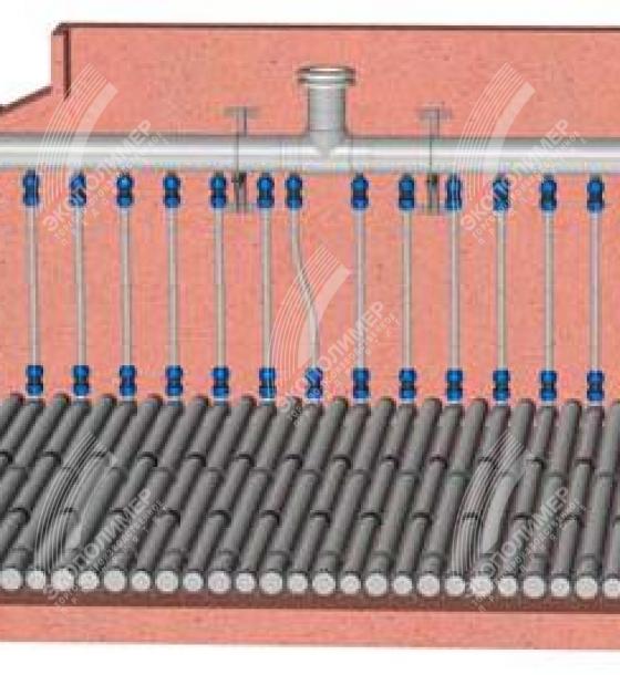
Distribution polyethylene manifold for high-rate filter with water-air flushing.
Basic parameters and dimensions of the AFM APM-DF
Table 2
Parameter | AFT APM DF-65 | AFT APM DF-90 | AFT APM DF-100 | AFT APM DF-115 | AFT APM DF-135 |
AFT APM DF length, mm | up to 3100 | ||||
Drainage branch length, mm | Determined by the filter bed dimensions | ||||
Outer diameter of the dispersing layer, mm | 112±2 | 130±4 | 146±4 | 160±4 | 180±4 |
Inner diameter of the frame pipe, mm | 65±2 | 90±2 | 100±2 | 115±2 | 135±2 |
Operating pressure, atm | 0.5-5 | ||||
Operating temperature, °C | up to 60 | ||||
Loss of head in flushing, m H2O | 1.0 – 5.0 | ||||
Frame pipe wall thickness (along the ribs), mm | 12 | 14 | 16 | 18 | 20 |
Number of longitudinal channels of the frame pipe, un. | 12 | 12 | 14 | 16 | 18 |
Maximum filtrate load, m3/h per 1 m of drainage system | <9 | <20 | <25 | <32 | <45 |
Specific technical water load, m3/h per branch | <28 | <45 | 45-55 | 55-75 | 75-105 |
Specific filter surface of the drainage filter m²/linear meter. | 0.35 | 0.41 | 0.46 | 0.5 | 0.57 |
Uneven water distribution along the branch length, % | up to 5% | ||||
Pore diameter of porous-filtering layer, mm | 0.1–0.2 | ||||
Basic parameters and dimensions of the AFM APM-AF
Table 3
Parameter | AFM APM- |
AFT APM-AF length, mm | up to 2000 |
Outer diameter of the dispersing layer, mm | 112±4 |
inner diameter of the support pipe, mm | 65±2 |
Operating pressure, atm | up to 8 |
Operating temperature, °C | up to 60 |
Loss of head in air supply to the aerator during flushing, m H2O | up to 1.0 |
Effective pore diameter of dispersing layer, mm | 0.1–0.2 |
AFT APM-AF 1 linear meter air throughput capacity, m3/h | < 50 |
Air distribution branch specific air load, m3/h | <180 |
Basic parameters and dimensions of the AFM APM-TF
Table 4
Parameter | AFM APM TF-65 | AFM APM TF-90 | AFT APM TF-100 | AFT APM TF-115 | AFT APM TF-135 |
The pipe filter length corresponds to the ATF APM-TF drainage branch length, mm | The pipe filter length is not limited and is determined by the dimensions of the filter bed | ||||
Outer diameter of the pipe filter, mm | 98±2 | 116±2 | 132±2 | 146±2 | 166±2 |
Inner diameter of the pipe filter, mm | 65±2 | 90±2 | 100±2 | 115±2 | 135±2 |
Operating pressure, atm | 0.5-5 | ||||
Operating temperature, °C | up to 60 | ||||
Loss of head in flushing, m H2O | 1.0 – 5.0 | ||||
Frame pipe wall thickness (along the ribs), mm | 12 | 14 | 16 | 18 | 20 |
Number of longitudinal channels of the frame pipe, un. | 12 | 12 | 14 | 16 | 18 |
Specific technical water load, m3/h per branch | <28 | <45 | 45-55 | 55-75 | 75-105 |
Uneven water distribution along the branch length, % | up to 5% | ||||
The drainage and distribution and air distribution branches are mounted parallel to each other and stacked alternately.

Drainage filter branches
A free end of the drainage filter or aerator in the AFT branch is plugged, pipes are assembled into the system with the use of threaded couplings. The assembling scheme of the drainage filters into the branch is shown in Fig. 5.

Drainage filter branch assembling
1 - steel coupling; 2 - drainage filter; 3 - connecting coupling;
4 - plug; 5 - support; 6 - adjustable element
The aeration system is attached to the air distribution manifold by means of polyethylene branch pipes with setoffs (see Fig. 10, item 1). For the rest, the assembling scheme of the aeration branch is similar to the drainage branch assembling scheme.
Aerator branches

Air flushing aerator branch assembling
1 – branch pipe with offset; 2 – aerator; 3 – connecting coupling; 4 – plug; 5 - support