Ecopolymer equipment for mechanical wastewater pretreatment
30. 01. 2018
The experience of using the rake screen design [1] developed by Ecopolymer has shown that it is most effective to use it together with the equipment for processing the screen-trapped waste. Therefore, a set of equipment for mechanical pretreatment of wastewater has been developed, consisting of RTO mechanized rake screens, EVK screw conveyor and EPVP screw press (Scheme 1)

Scheme 1. Mechanical wastewater pretreatment system
1 – EVK screw conveyor; 2 – RTO mechanized rake screens; 3 – wastewater channels; 4 – EPVP screw press
The design of RTO mechanized rake screens has been substantially modernized and improved in recent years. The main tasks facing the specialists of the enterprise during these works were:
- enhancement of the screen reliability, and, as a consequence, increased warranty period of operation up to 5 years;
- improvement of the screen manufacturability and the resulting reduction of terms of manufacture;
- improvement of the screen maintainability, increase in its service life up to 10 years or more;
- improvement of wastewater treatment quality and efficiency.
- better attractiveness of the screens for operating organizations due to the level of their automation, ease of installation and maintenance.
To achieve these goals, the filter screen and the screen rakes were the first to be upgraded.
An upgraded filter screen is a set of rectangular bars – slats, installed with a certain pitch (spacing). The filter screen is the central unit of the screen. It is important that the modernization has provided a quick replacement of one or more damaged (deformed) slats directly on the operation site, without dismantling both the filter screen from the rake screen itself and other parts thereof. This effect was achieved thanks to the patented original design of the filter screen, namely the method of slat fixation (Scheme 2).

Scheme 2. Upgraded filter screen
a - a drawing from the patent for the filter screen design; b - fixing of the slats with a fixing angle at the manufacturing stage (before etching of welded seams)
Unlike most similar structures, the fixation of the slats is not rigid welded, but free inlaid, so they do not bend under load. Such a design solution, in addition to improving the maintainability of the screen and increasing its service life, has allowed abandoning the stiffeners (which are concentrators for the formation of “waves" from fibrous inclusions) and in general enhancing the reliability of equipment. The slats are made by laser cutting and delivered immediately for assembly without any additional processing.
Rakes are the main element of the filter screen cleaning system, designed to remove contaminants trapped in front of the lamellas or stuck in the gaps between them. They determine the quality and efficiency of mechanical wastewater treatment. Therefore, upgrading made the improved rakes (Scheme 3), as well as the filter screen, dismountable, and the rake elements – teeth and blades, responsible for the screen cleaning, - able to clean the gap between the slats to its full depth (slat width). The new design of dismountable rakes has been also patented.

Scheme 3. Upgraded dismountable rake
1 – blade-fixing bar; 2 – rake platform; 3 – teeth; 4 – blades; 5 – filter screen slats
In addition to the rakes, the cleaning system of the filter screen includes two endless plate traction chains with hollow cylinders made of stainless steel and rolls made of polymer material, a drive shaft with drive sprockets and lower guides made of the same material as the chain rollers. Particularly important in upgrading the filtration screen cleaning system was its reliability and durability. As a result, a modern wear-resistant and swelling-proof polymeric material was selected for the rollers and lower guides. The chain design complies with GOST 588-81 (type 3, version 3).
When operated, the bottom of the screen rests on the bottom of the channel, and the screen above the channel rests on the racks, which are fixed to the concrete floor or the metal framing of the channel with anchors. Such a fastening makes it possible to perform the installation of the screen without emptying the channel. The racks and the screen are connected with swivel joints, which allows placing the screen in a horizontal position above the channel for its maintenance. For ease of installation and maintenance, the rack with swivel supports have been upgraded - the swivel joint has been made detachable, which further facilitates the installation of the screen, and the height of the racks can be adjusted.
The screen is equipped with a control system, consisting of a control cabinet, remote control, ultrasonic level sensor, and a drive stopping proximity sensor. The control system ensures both manual and automatic operation of the screen, as well as protection against abnormal situations (electronic motor overcurrent protection) by disconnecting the drive power and giving an emergency light signal.
Automatic control of the screen is provided by a programmable logic controller that displays information about its status (operation, emergency shutdown, etc.) to the control panel or allows the screen operation to be fully integrated into the automated process control system using standard communication protocols. Also, the control system can also regulate the speed of the drive (the speed of the rakes) by using a frequency converter, and thus adjust the operation of the screen according to the individual conditions of the operation object.
The operation of the screen in automatic mode is cyclic - the cleaning mode alternates with a pause. The screen goes to cleaning mode on a controller signal, which sets the operating time and pause, or on a signal from the ultrasonic screen inlet water level sensor (whichever occurs first).
The controller-based control system of the screen allowed for development and application of an intelligent system for automatic unclogging of the filter screen. The principle of this system is as follows:
- in case of abnormal situation, when the rake cannot lift large-scale waste trapped, or a rake tooth is jammed between the screen slats, the screen drive shaft is stopped by the torque clutch, integrated in the drive. The control system receives a corresponding signal from the non-contact drive stopping sensor;
- the drive automatically switches to reverse rotation, which causes the rakes to move in the opposite direction, with the greater pitch then the set one, thereby automatically eliminating the cause of an abnormal situation;
- if the cause of the rake stop is eliminated, the drive automatically switches to forward run;
- if the cause is not eliminated and the rakes stop again, the auto-reverse cycle is repeated up to three times;
- If, after three auto-reverse cycles, the cause of the rake stop is not eliminated, or the movement of the rake is difficult both in the forward and reverse directions, the screen stops with the generation of the light and sound signal "Failure".
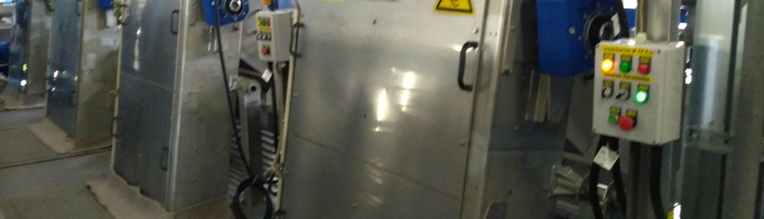
Fig. 4 shows the operating screen (one of the first with upgraded design), which was installed in Tyumen in February 2013.


Fig. 4. One of the first screen with upgraded design
Ecopolymer put its own design of EVK screw conveyor into production in 2012. Before that, the mechanical pretreatment systems were equipped with similar, usually import equipment.
The design of the screw conveyor has been based on constructive solutions of other manufacturers, as well as the wishes of the operating organizations.
As a result, the EVK screw conveyor design has acquired the following features:
- the conveyor housing is made of separate unified sections in the form of a semicircular chute;
- in terms of functions performed, the unified sections can be transport, feeding and discharging;
- the housing is closed with easily detachable covers;
- the lining of the conveyor is in the form of replaceable liners of 1 m length, made of wear-resistant plastic;
- the axial-less screw is made of wear-resistant high-alloy steel, using the method of continuous deformation, rather than welding of individual flights;
- the unified conveyor supports are height-adjustable and can be attached to the housing anywhere during installation;
- The conveyor operation is fully automated and adapted to work with other equipment included in the mechanical wastewater pretreatment system.

Fig. 5. The layout of the unified screw conveyor
1 - protective guard of the feeding section; 2 - feeding section with funnel; 3 - transport section with lid
Fig. 5 shows the layout of the unified screw conveyor, and Fig. 6 shows inclined screw conveyor during assembly at Ecopolymer TME facilities.

Fig. 6. Inclined screw conveyor during assembly at Ecopolymer TME facilities
Screw flushing presses combine several functions. They are designed for flushing, compacting and transporting waste removed from wastewater on screens to a manifold. Waste washing is carried out in order to return the organic soluble substances contained therein to the process of biological wastewater treatment.
The assimilation of the production of the EPVP screw flushing press was carried out simultaneously with the EVK screw conveyor. Before the development of the press and the conveyor, a number of constructive solutions of other manufacturers were analyzed, the experience and wishes of the operating organizations were studied. As a result, it was decided to maximally reduce the content of solid inclusions in the squeezed and technical water, and to provide, if necessary, the lifting of the dehydrated waste to a height of up to 5 m, to automate the operation of the press as much as possible.
The basic design of the EPVP press is shown in Scheme 7. The supply of screen-trapped waste to the EPVP is carried out through the intake opening in the housing, to which the hopper is attached. The press is divided into a waste feeding and washing zone and a pressing zone. The axial-less screw with variable pitch is driven by the drive. The rotation speed of the screw (drive) is adjustable. When rotating, the waste moves inside the perforated basket (cylindrical shape) from the feeding and washing zone to the pressing zone and then through the discharge pipe to the manifold. The size of the basket perforations and their shape are designed so as to ensure the smallest content of solid inclusions in the squeezed and technical water.

Scheme 7. Basic design of the EPVP press.
1 – screw; 2 – intake opening; 3 – hopper; 4 – sludge washing nozzle; 5 – sieve; 6 – drive; 7 – pressure chamber; 8 – discharge pipe; 9 – sieve washing nozzles; 10 – sump; 11 – sump washing nozzle; 12 – drain pipe.
In the pressing zone pressure on wastes washed from organic matter rises due to a gradual decrease in the pitch of the axial-less screws. At the end of the pressing zone, an additional compression chamber is arranged between the screw end and the discharge pipe. The volume of the chamber is calculated based on the requirements for the lifting height washed and pressed waste and their moisture content. Further, the washed and pressed waste is fed into the discharge pipe, and from there to the manifold.
A EPVP design has been developed that allows transporting compressed and washed waste to a height of up to 5 m at an angle of not more than 75°. This is ideal when it is impossible to place the manifold directly in the room of the mechanical treatment shop at the same level with the EPVP.
The waste washing and equipment flushing system consists of injectors and a control unit with the appropriate piping. Nozzles designed for washing soluble organic from waste are installed above the screw. The nozzles designed for periodic cleaning of the outer surface of a perforated sieve and a press sump are placed in the lower part of the press, in the space below the perforated basket. When lifting washed and pressed waste to a height of more than 2 m at an angle greater than 45°, additional nozzles are provided to the discharge pipe, which slightly moisten from time to time the surface of the removed waste.
The squeezed from waste water together with technical water, containing washed dissolved organic, is sent back to the screen inlet channel. The operation of the screens, conveyor and press in the mechanical pretreatment system by Ecopolymer is fully coordinated both in manual and automatic modes.
Since the start of production of the EVK conveyor and the EPWP press, the mechanical wastewater treatment systems have been manufactured, installed, launched and successfully operated at wastewater treatment facilities and sewage pump stations in the cities of Orsk, Tobolsk, Severodvinsk, Volgograd, Veliky Novgorod, Gubkin, Alagir, Moscow, Kolomna, Brest, Novaya Kakhovka (Ukraine), Karaganda (Kazakhstan), and others. Fig. 8 shows one of such complexes in Kolomna, Moscow region. A feature of this facility is the pressing of pressed waste to a height of 5.3 m beyond the mechanical treatment room.

Fig. 8. Ecopolymer mechanical wastewater pretreatment system